
|
Workflow Tab |

Workflow Tab |
Properties of Objects |

|
 Workflow Tab
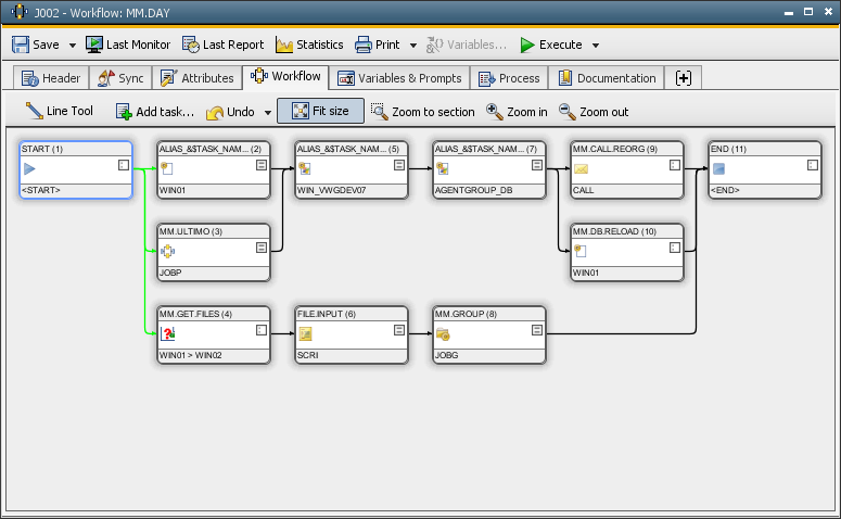
The Workflow tab is object-type specific and is only available in standard-type Workflow objects. You can use it to edit the workflow and to define the dependencies of the individual tasks to each other.
Object: Workflow
Object class: Executable object
Object type
(short name): JOBP
Watch our introductory video on using Workflows in the Automation Engine online:
[Editing a workflow] [Appearance of a workflow]
Adding Tasks
In the Workflow tab, a newly created workflow only includes the tasks "START" and "END". You can add additional tasks to this workflow by highlighting
one or more objects in theExplorerand dragging
them to the Workflow tab. When you press and hold the ALT key, the task will be added as an external dependency.
If specified in your UserInterface settings, the "Add task" dialog opens in which you can also assign an alias name. By default, this function is deactivated.
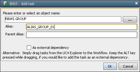
Alternately, you can use the context-menu command Add task. A dialog opens in which you can enter the name of the object that should be inserted or select it directly from a small Explorer window by clicking the "..." symbol. You can also assign an alias name that should be used to display the task in the workflow. If you activate the check box, the object will be inserted as an external dependency and not as a direct part of the workflow.
You can also set and modify the alias name of workflow tasks in the workflow's properties.
Predefined variables, placeholders for Variable objects andobject variables (of the workflow) can be used as a part of the alias name. Using invalid variables results in an error when the workflow starts.
Objects that are not active by definition (Header tab) will be skipped when the workflow is being processed. A query appears in the UserInterface when you try to insert an object in the workflow.
Deleting Tasks
You can delete objects that are no longer required in a workflow. Highlight
them and use the DEL key or the Remove
command in the context menu.
Copying Tasks
When you want to include a task in a workflow several times, you can highlight it
within the workflow and drag it (shift key pressed) to an empty position. By doing so, you create a copy of the task that includes all the specified attributes. Alternately, you can also use the corresponding context-menu command.
Note that you can copy individual tasks or task
sequences and insert them in other workflows.
Replacing Tasks
Tasks of a
workflow can be replaced by other tasks. Highlight an object in
the Explorer and drag it to the workflow task that should be replaced. A query appears which must be confirmed. "No" means that the new task will be moved to an empty position in the workflow.
Moving Tasks
You can move tasks that are in the Workflow tab by holding the mouse button pressed. If you want to move several tasks at a time, you can either group them in a frame or use the CTRL key. When the mouse pointer displays arrow symbols, you can move the selected tasks in blocks through a non-visible raster. You can also add lines and columns to this raster. Move the mouse pointer to the position where a row or column should be inserted and select the suitable popup-menu command. You can also remove lines and columns that do not include tasks in the same way.
Linking Tasks
Workflow tasks usually depend on other tasks and have one or more predecessors
and/or successors. You can define dependencies by linking tasks with the
Line Tool (see Settings of the UserInterface).
Use the corresponding context-menu command to call the Line Tool.
The mouse pointer now displays a pen symbol. Press and hold the mouse and move it from a particular task to the task that should be the successive task. Make sure that you keep the correct order, especially if the tasks that should be linked are positioned one below the other.
There is a simple method that can be used in order to link tasks to several other tasks. For example, task A should be linked to the tasks B, D and D:
In order to link objects that are positioned one below the other to one common successor or predecessor, Automic recommends applying the following method:
1. Activate the Line Tool.
2. Highlight the tasks by drawing a rectangle around them (Shift key pressed, release the key when the tasks have been highlighted).
3. Draw a line from one of the highlighted task to a required tasks. By
doing so, the lines are automatically drawn from all highlighted tasks to
the required one.
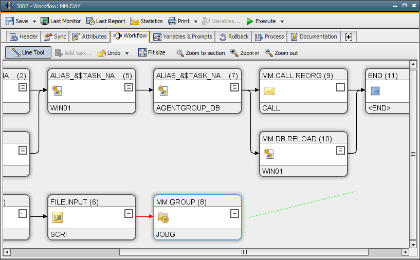
The linking lines to predecessors are displayed in red, the linking lines to successors in green. You can highlight linking lines between objects by clicking them or by using the line tool. They are displayed in yellow. You can use the DEL key or the appropriate context-menu command to delete lines.
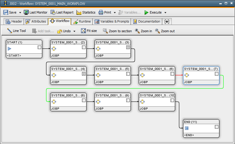
Splitting Task Sequences in several Lines
Within a workflow, you can also arrange long task sequences (serial
processing) in several rows. Doing so makes it easier to edit the workflow
and as a result, the monitor is more clearly structured.
Tasks in a row (they are positioned one below the other) can easily be linked:
Vice versa, you can also draw a line from a line to a line that is positioned above:
Do not intersect linking lines, especially if you use several lines for the serial processing of tasks. Arrange individual tasks in a way that the lines do not intersect.
Defining Dependencies
You can access the properties of tasks in the context menu and specify
numerous conditions
and dependencies.
[Editing the workflow] [Appearance of the workflow]
There is a "classical" and a "default"
workflow view. You can specify the view that should be used to open workflows in the UserInterface's properties . You can always switch between the two available
views by clicking the  symbol in the menu bar.
Size and appearance
of the workflow
You can change the workflow's size and appearance any time by using
the following buttons:
|
Symbol |
Description |
|---|---|
|
|
Adjusts the layout to fit the size of the workflow. |
|
|
Enlarges the layout in proportion to the workflow size (scroll bars appear if necessary). |
|
|
Reduces the layout in proportion to the workflow (scroll bars appear if necessary). |
|
|
You can frame and enlarge an area by holding down the left mouse button (the cursor takes the form of a loupe). |
The workflow view can also be maximized or minimized by using the CTRL key in combination with the scroll wheel. This view is kept until you change it or close the window.
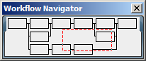
When you enlarge the workflow so that it cannot completely be displayed anymore, it is helpful to use the Workflow Navigator. It appears automatically and you can select the workflow section that should be displayed in the tab. Click the required section in the JP Navigator or move and hold the red frame.
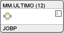
Display of Tasks
The box that symbolizes the task informs about the object type. The symbol that appears in the right part of the box includes information about stored task properties. No properties are stored in the following job:
The following illustration shows the same job as above but now it includes properties.
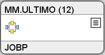
Click the  or
or  symbol in order to open the properties windows.
If a job has no agent because is has been imported from a different AE system or client, a question mark displays instead of the platform symbol.
Based on the expected runtime, the workflow's monitorvisualizes the task's progress with a colored bar.
Information about the properties of a workflow task is provided in the form of tooltip texts. If you move the mouse over a box, a tooltip window opens. Depending on the UserInterface settings and the zooming factor, it starts with an illustration of the box followed by a section that provides general information about the task (for example, the target agent). The tooltip window also includes the exact information about all the settings that are defined in the properties window. In theUserInterface settings, you can define the tabs that should be included in the tooltip window.

Note that the task boxes of objects that have been deleted are displayed white.
The "Properties" information that is included in the tooltip is composed of one or several letters and describe the task's properties:
Modifications that you make in objects (for example, you use a new host or a Sync object) immediately appear in the workflow's graphical display.
Printing
You can use the context-menu command Print Chart... in order to print the workflow's graphical display. Specify
the maximum number of pages that should be printed. The optimum size is automatically calculated.
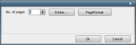
Note: A printer needs to be installed and connected to the computer. This option is not available if no printer is installed. Specified print formats are ignored.
See also:
External Workflow Dependencies


